

zencontrol
Smart PWM Field Dimmer 10A 4 Channel Wired and Wireless
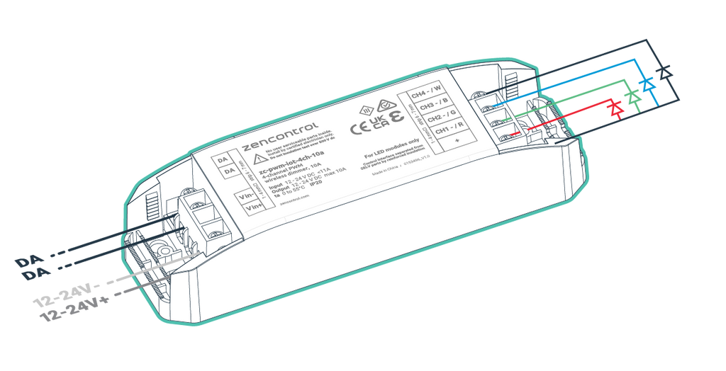
Order code: zc-pwm-iot-4ch-10a
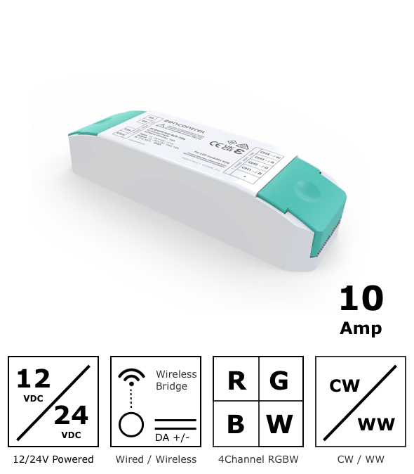
Designed to support 12 - 24V DC LED strips
- Maximum power capacity 240W (10A x 24V)
-
For use with DALI control system
- Compatible with DALI and DALI-2
-
Supports IEC 62386-104 over Thread®
-
Can be configured as 4 channel LED, 2 x tunable white or RGBW controller
-
Large pass through terminal blocks for easy wiring
-
Protected against DALI over voltage
-
Converts DALI ECGs and ECDs to a wireless system
-
Compliant to IEC 62386-208 and IEC 62386-209 (TC, RGBW)
-
DALI device type 6 and type 8
Specification
| Supply Voltage | 12 - 24 Vdc |
| Control system | Wired DALI-2 Wireless IEC62386-104 over Thread |
| Radio Support | IEEE 802.15.4 |
| Frequency band | 2.4 GHz |
| Max radio tx power | +8 dBm |
| DALI line current | 2 mA |
| Output type | 10A total (0-10A per channel) |
| Output load type | LED only |
| Independent channels | 4 |
| Bus unit configurations | 4 x DT6, 2 x DT8-TC, DT8-RGBW (see bus unit configuration table on datasheet) |
| Wiring | 1-4 mm2 Strip 6-7mm |
| Operating temperature | 0 to 55°C |
| Material | PC |
| Classification | Class II |
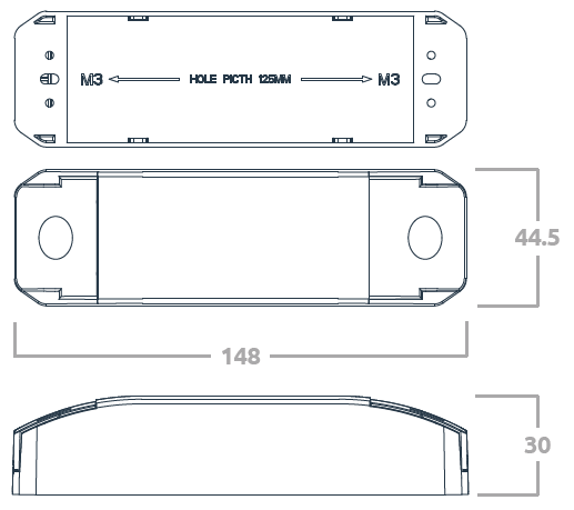
| Mounting | Independently mounted control for surface mounting |
| Ingress protection | IP20 |
Configuration Options
Standalone Wired or Wireless
The Smart LED PWM Dimmer can be used on a standalone DALI-2 network, or a standalone wireless bluetooth network for small configurations and simple systems.

Wired 101 mode
101 mode is enabled after a 101 power supply has been connected to the DALI terminal and the device has not been added to a 104 application controller.

Wireless 104 mode
104 mode is enabled after the device has been added to a 104 application controller such as zc-iot-fc.

Bridge mode 104 + 101 mode (Wireless and Wired)
The same functionality as a the wireless system, however with the ability to connect wired DALI-2 devices to the Smart LED PWM Dimmer and have those DALI-2 devices appear and be programmed on the wireless network.
104 + 101 bridge mode is enabled after the device has been added to a 104 controller and a 101 power supply has been connected to the DALI terminals.
